

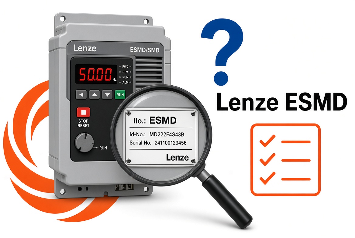
Lenze SMD frequency inverters, also identified by model numbers beginning ESMD, are used in a wide range of industrial motor control applications. Like other variable speed drives, they can display fault codes and status messages when a problem occurs or when operating conditions prevent the motor from running.
Understanding these messages can help engineers and maintenance personnel identify the cause of a problem and determine the appropriate action.
This guide covers common Lenze SMD / ESMD fault codes, their possible causes and recommended troubleshooting checks, using the standard Lenze SMD operating instructions as a reference.
If you are experiencing problems with an older Lenze drive, Modern Drives & Controls can also help with technical advice and replacement options.
Identifying your Lenze SMD / ESMD inverter
Before investigating a fault, it is important to identify the inverter correctly.
Lenze SMD drives are commonly identified by model numbers beginning with ESMD, followed by additional characters indicating the particular drive specification.
The model number and electrical ratings can normally be found on the drive's nameplate.
When investigating a fault, it is useful to record:
-
The complete inverter model number.
-
The displayed fault or status message.
-
The motor rating and application.
-
Whether the fault occurs during starting, running or stopping.
-
Any recent changes to the motor, wiring or machine operation.
This information can help narrow down the cause of the problem.
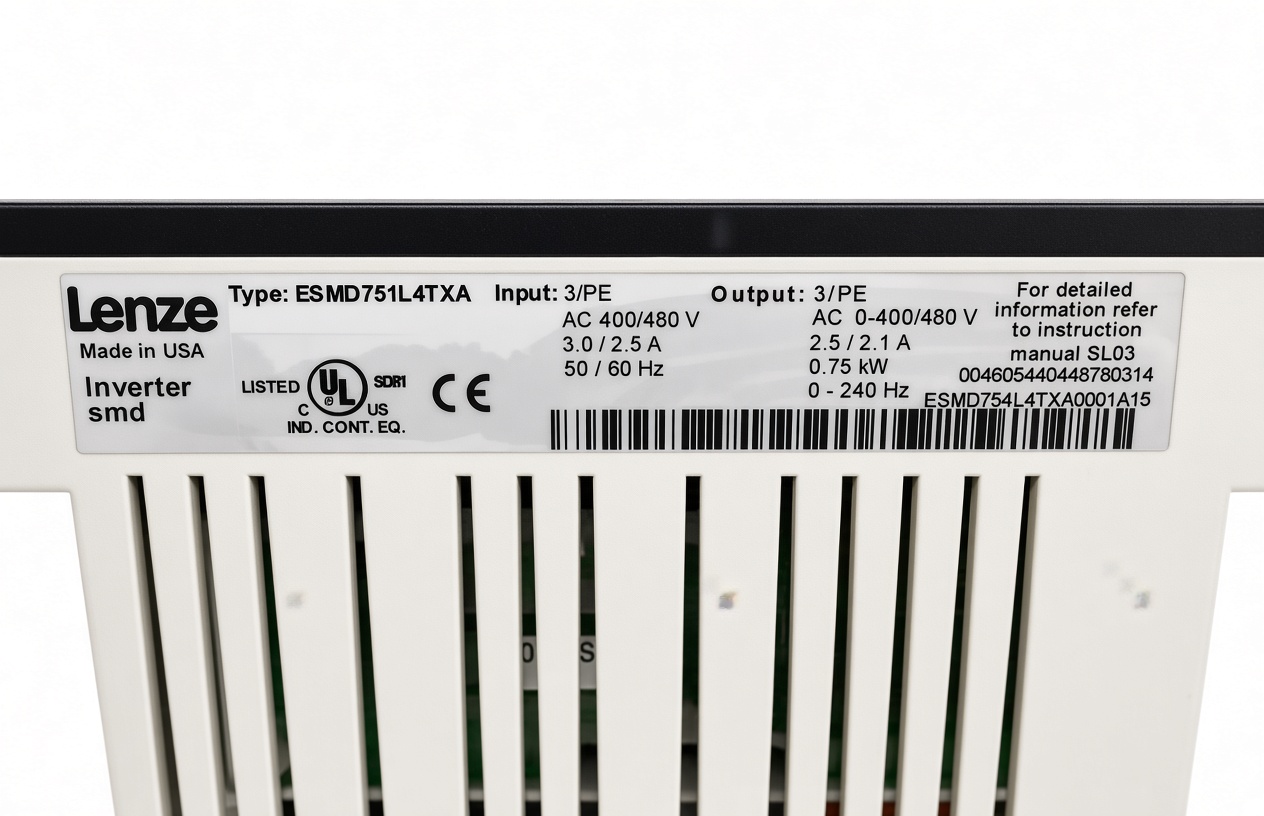
Lenze SMD / ESMD fault codes and explanations
The following fault codes are taken from the standard Lenze SMD operating instructions. The explanations describe the causes and checks identified by Lenze.
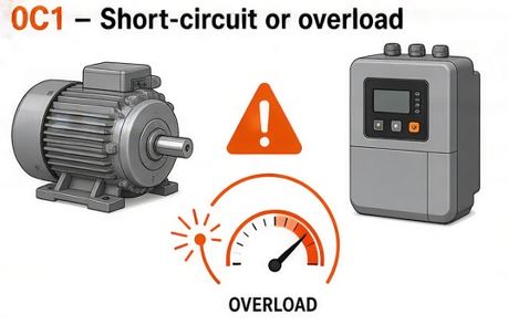
0C1 – Short-circuit or overload
Possible causes:
-
Short-circuit in the motor cable.
-
Excessive capacitive charging current in the motor cable.
-
Acceleration time set too short.
-
Defective motor cable.
-
Internal motor fault.
-
Frequent or prolonged overload.
Recommended checks:
Inspect the motor cable and connections for damage or short-circuits. Check the motor for possible faults and review the acceleration time setting.
Where motor cable length or capacitance is excessive, the cable installation may also need to be reviewed. Check that the inverter is correctly selected for the motor and application.
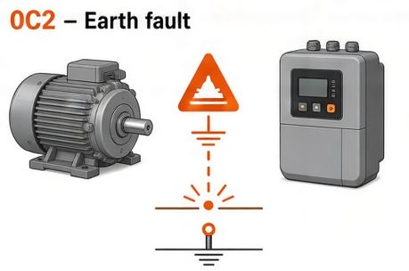
0C2 – Earth fault
Possible causes:
-
A motor phase connected to earth.
-
Excessive capacitive charging current in the motor cable.
Recommended checks:
Check the motor cable and motor for earth faults. Inspect the wiring and connections for damage.
Where necessary, a suitably qualified person should carry out insulation and earth-fault testing.
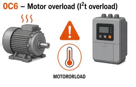
0C6 – Motor overload (I²t overload)
Possible causes:
-
Motor operating above its permissible continuous current.
-
Frequent or excessively long acceleration periods.
-
Incorrect inverter selection for the application.
Recommended checks:
Check the motor load and operating conditions. Confirm that the inverter is correctly rated for the motor and application.
Lenze also identifies parameter C20 as relevant to this fault, so its setting should be checked against the motor and drive requirements.
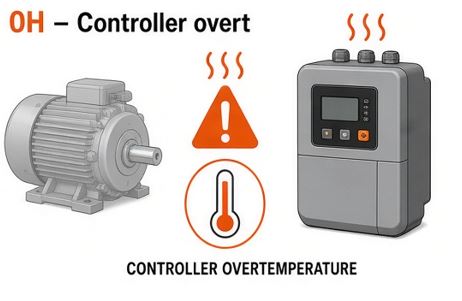
0H – Controller overtemperature
Possible cause:
The inverter is too hot internally.
Recommended checks:
Check the installation environment and ventilation around the drive. Look for restricted airflow, excessive ambient temperature or operating conditions that place too much load on the inverter.
Check that the drive is correctly rated for the application.
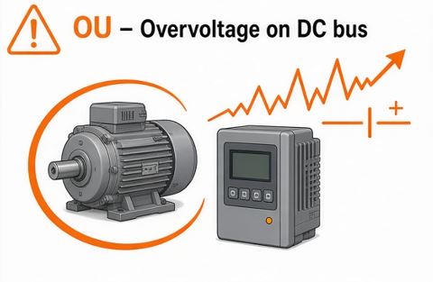
OU – Overvoltage on DC bus
Possible causes:
-
Mains supply voltage too high.
-
Deceleration time too short.
-
Motor operating in generator mode.
-
Earth leakage on the motor side.
Recommended checks:
Check the incoming supply voltage and review the deceleration time setting.
If the motor is regenerating energy during deceleration, the braking arrangements may need to be reviewed. Inspect the motor cable and motor for possible earth leakage.
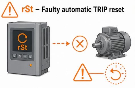
rSt – Faulty automatic TRIP reset
Possible cause:
More than eight errors have occurred within ten minutes.
Recommended checks:
Identify the original fault responsible for the repeated trips rather than simply attempting to reset the inverter.
The appropriate corrective action depends on the underlying fault.
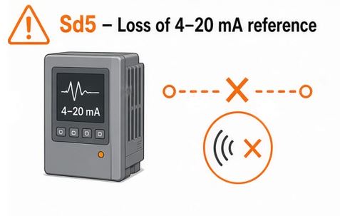
Sd5 – Loss of 4–20 mA reference
Possible cause:
The 4–20 mA reference signal has fallen below 2 mA when parameter C34 is set to 4.
Recommended checks:
Check the analogue signal source and wiring. Inspect connections and confirm that the 4–20 mA reference signal is present and operating correctly.
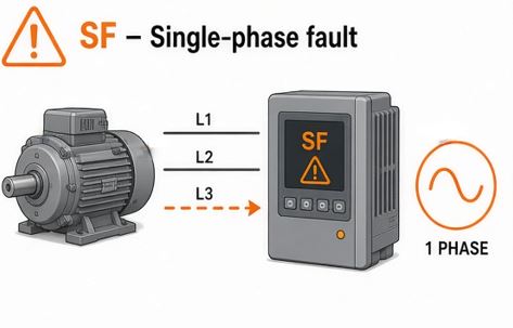
SF – Single-phase fault
Possible cause:
A mains supply phase has been lost.
Recommended checks:
Check the incoming mains supply and investigate the missing phase. Any electrical testing should be carried out by suitably qualified personnel.
Other Lenze SMD / ESMD error messages
The SMD inverter can also display other error messages relating to its electronic programming module, digital inputs, braking arrangements and communication systems.
| Display | Description | Possible action |
|---|---|---|
| cF | Data on EPM not valid | Check that the EPM contains valid data for the controller |
| CF | Data error | Investigate the EPM data |
| GF | OEM data not valid | Check the programmed data |
| F1 | EPM error | Power down and check or replace the EPM |
| CFG | Digital inputs not uniquely assigned | Check the E1–E3 digital input assignments |
| dF | Dynamic braking fault | Check the braking resistor and deceleration conditions |
| EEr | External error | Investigate the external TRIP input |
| F2–F0 | Internal fault | Contact Lenze or seek specialist technical assistance |
| FC3 | Communication error | Check serial communication connections |
| FC5 | Communication error | Specialist assistance may be required |
| JF | Remote keypad fault | Check the remote keypad connection |
| LC | Automatic start inhibited | Check the start condition and terminal 28 |
These messages should be investigated in accordance with the relevant Lenze operating instructions.
Lenze SMD / ESMD status messages
Not every message displayed by an SMD inverter indicates a fault. Some messages simply describe the current operating condition of the drive.
The following are examples of status messages identified in the Lenze operating instructions.
| Display | Meaning |
|---|---|
| 50.0 | Present output frequency, shown here as an example |
| OFF | Drive stopped, with outputs inhibited |
| 1nh | Drive inhibited |
| stP | Output frequency is zero |
| br | DC injection braking active |
| CL | Current limit reached |
| LU | DC bus undervoltage |
| dEC | DC bus overvoltage warning during deceleration |
| nEd | No access to the selected parameter |
| rC | Remote keypad active |
For example, a drive displaying br may simply have its DC injection braking function active. Similarly, OFF can indicate that the drive has been stopped by its control signal rather than having developed a fault.
Understanding the difference between a status message and an actual fault can help avoid unnecessary investigation or replacement.
Resetting a Lenze SMD / ESMD fault
Once the cause of a fault has been identified and corrected, the inverter may need to be reset before normal operation can resume.
The standard Lenze SMD instructions describe fault reset arrangements through parameter C70.
Depending on the configuration, a reset can be carried out following a LOW-HIGH signal change at terminal 28, a mains switching operation or a LOW-HIGH signal change at the digital TRIP reset input.
Automatic TRIP reset can also be configured through C70 and C71.
The correct reset method depends on the existing drive configuration.
Important: Do not repeatedly reset a drive without identifying the cause of the original fault. Repeated trips can indicate an underlying electrical, mechanical or application problem.
Electrical work and fault investigation must only be carried out by suitably qualified personnel. Lenze specifies that the drive's DC bus capacitors can retain a dangerous charge after the supply has been disconnected. Allow at least three minutes before touching electrical connections, and follow the drive's safety instructions.
When should you consider replacing a Lenze SMD / ESMD inverter?
The Lenze SMD range is an older inverter series, and replacement may be worth considering where a drive has developed a recurring fault, suffered an internal failure or become difficult to repair.
However, selecting a replacement is not simply a case of matching the original motor power rating.
Important considerations include:
-
Motor voltage and rated current.
-
Supply voltage and available phase configuration.
-
Required inverter control functions.
-
Speed control and application requirements.
-
Existing control panel wiring and installation arrangements.
-
Available space and mounting requirements.
A suitable replacement should be selected around the complete application rather than the original drive rating alone.
For further information, see our guide to Lenze SMD / ESMD inverter obsolescence and replacement options, or take a look at our Lenze i510 inverter range.
Technical support for Lenze SMD / ESMD inverters
Modern Drives & Controls Ltd has experience supplying Lenze variable speed drives and supporting industrial motor control applications.
If you are experiencing a fault with a Lenze SMD / ESMD inverter, need help identifying a fault message or are considering replacing an older drive, our technical sales team can help.
We can discuss the existing installation, motor requirements and application to help identify a suitable solution.
Contact Modern Drives & Controls to discuss your Lenze inverter requirements.